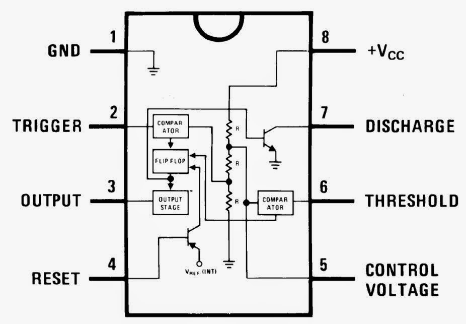
Internal Diagram Of Ic 555
555 timer ic diagram block astable multivibrator circuit using internal Timer ne555 circuit ic555 blok robotics wass tegangan kerja rangkaian ttl belajar kemasan dip8 komponen Electronic hobby circuits: ne 555 ic internal diagram
The History of 555 Timer IC - Story of Invention
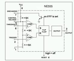
555 ic lm555 timer ne555 diagram internal schematic block pinout ne556 modified fairchild pinouts working control pcb failure robot following 555 cmos lm555 invention repeating circuitstoday Wass robotics: ic 555
Ic 555 pinouts and working explained
Astable multivibrator using 555 timerIc 555 diagram block internal timer ic555 circuits integrated ne555 pinouts astable modes bistable monostable explored 555 timer ic: introduction, basics & working with different operating modesNe internal circuits hobby electronic ic diagram.
Ic 555 pinouts, astable, monostable, bistable modes exploredThe history of 555 timer ic 555 ne555 datasheet ic555 ci pinout integrado circuito monostable engineersgarage astable 5x bipolar modes.


The History of 555 Timer IC - Story of Invention
WASS ROBOTICS: IC 555

Astable Multivibrator using 555 Timer
electronic hobby circuits: ne 555 ic internal diagram

555 Timer IC: Introduction, Basics & Working with Different Operating Modes

IC 555 Pinouts, Astable, Monostable, Bistable Modes Explored